Improving Beverage Security and Quality via Protection of Carbonation Co2

By David Porter

In the commercial environment of continuous improvement and quality assurance in beverage production, the issue of carbonation gas quality has had some attention in recent years. Additionally, there have been other concerns regarding ’product security’, which have resulted in understanding that achieving and maintaining a consistent flow of high quality CO2 from production facility to finished carbonated beverage is of high importance.
Contaminant Sources
CO2 is an unusual industrial gas in that it is produced from a wide variety of processes, and in some cases, as a by product of the production of an other chemical. Each process has the potential of leaving a residue of either the feed chemicals or the product chemical in the CO2 stream, the purity of which is therefore reduced.
The major gas companies have built purification processes into their CO2 production or recovery plants to reduce these potential contaminants. However, occasionally contaminants remain in the CO2 and are delivered to the beverage production facility. Additionally, geographical variations exist in the quality and reliability of CO2 supplies. Finally, contaminants may be introduced into the CO2 after it has left the production facility from the storage and transport vessels or from mishandling. Bearing this in mind, it is possible that CO2 supply may include a wide range potential contaminants, which complicates detection and control strategies.
Beverage CO2 Specification
The contaminants of interest and their critical limits are identified in the ISBT Carbon Dioxide Quality Guidelines (Ref 1). A sub-set of requirements is included in Table 1.
These levels closely correspond to those published by the Compressed Gas Association (CGA) (Ref 2) and the European Industrial Gases Association (EIGA) (Ref 3), and are becoming widely recognised in the beverage industry worldwide. The three contaminants selected for test in this article are:
Benzene: A key member of the aromatic hydrocarbon group regulated by statutory requirements.
Acetaldehyde: An oxidizing agent and specifically named potential contaminant of CO2 that may affect flavor and storage life of the beverage.
Hydrogen Sulfide: A key member of the total sulfur group with a pungent odor that will readily be detected by beverage consumers.
Quality Monitoring Procedures
Making a measurement of any contaminant at ppm (or sub ppm) concentration level is an involved process requiring particular care and attention. Measurements may be made using chemical indicator tubes that indicate, via a color change, the concentration of specific contaminants. Several companies supply tubes for the contaminants of interest. However, the indicating tubes may not have a minimum detection level low enough to ensure compliance with the critical limits and the levels of precision are typically 10 to 20 percent of reading range. Therefore, more sophisticated measurement methods are generally required.
For the above chemical contaminants, gas chromatography followed by a sensitive detector (eg. mass spectrometer) is commonly accepted as the analytical method of choice. The instruments are designed to measure low concentrations of one gas in another carrier gas and can be calibrated and set up specifically for the contaminants of interest. Larger beverage plants may have an inspection lab capable of undertaking such measurements or may have automated systems running gas analysis samples in (almost) real time.
Many plants, however, will not be in a position to make such an investment. In this case, a system of regular sampling and off-site analysis in conjunction with more straightforward on-site measurements is a practical alternative. This raises an important operational question, what should the plant do while waiting for the ’OK’ from the analysis laboratory; continue or halt production? An in-line CO2 protection unit has been designed to resolve this conundrum.
In-Line CO2 Purification
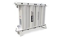
In order to tackle and provide protection against the wide variety of potential contaminants, a protection unit was designed containing a mixed bed of specially selected absorbent materials. These are pre-loaded into cartridges that enable easy removal and replacement at the end of their in-service life. As the housing is constructed from bolted high-tensile aluminium-extruded components, the protection unit’s capacity may be readily matched to the required process flowrate by adding or removing adsorption cartridges and columns. The protection unit processes the CO2 in its gaseous phase and is installed after the vapouriser.
Performance Verification
As performance of an in-line protection unit could not be practicably verified by deliberately introducing contamination into the CO2 flow at an operating beverage plant, removal verification was undertaken off-line in a laboratory. This allowed high levels of contamination to be introduced (approximately 10 times the levels set in the ISBT standard) and suitable contamination measuring techniques to be used.
The following test rig arrangement was used to mix, in a set dilution ratio, specially prepared gas mixtures and clean CO2. The deliberately contaminated CO2 was then flowed through a scaled purification unit at a set pressure and flowrate with gas samples being taken at locations directly upstream and downstream, typically on a daily basis.
After approximately 180 hours, the contaminated gas was removed and only the clean CO2 was allowed to pass through the protection unit. Inlet and outlet gas samples were again taken to confirm that the contaminants removed earlier in the test were not released to contaminate the otherwise clean CO2 flow. The aim of this section of the test was to verify that previously adsorbed contaminants were not desorbed.
Results
In the graphs, the inlet contaminant concentration (shown in red) was targeted at 10 times the allowable concentration set by the ISBT. The ISBT specification levels are also illustrated (shown in green). For the contaminants studied here, most of the inlet samples were in the eight to 12 times the ISBT specification while the outlet concentration was less than one-tenth of the specification. This results in a reduction in contamination concentration of 80 to 120 times.
All of the graphs show slight variations in the measured inlet contaminant concentrations. This could be due, for example, to small variations in the gas flows forming the contaminant mixture and its effect on the resulting concentration. Additionally, the low contaminant concentration levels seen throughout the work should be born in mind, with many results in the parts per billion range. In several cases, the outlet concentration was below the limits of detection of the analytical method for that contaminant; in these cases the concentration reported is the minimum detection level.
The point of discontinuing the flow of contaminated CO2, typically after approximately 180 hours, is indicated on each graph. The switch from contaminated to clean CO2 streams, for each of the contaminants discussed here, did not cause any detectable release of previously removed contamination. This simulates a delivery of clean, in-specification to a plant after processing some contaminated CO2.
The graphs also show that some residual adsorption capacity remains in the unit as no evidence of contaminant breakthrough was seen. This provides a useful safety factor, given the unquantified nature of potential quality excursions occurring during the unit’s working lifetime, in a real application.
References
  1. ’Carbon Dioxide Quality Guidelines and Analytical Procedure Bibliography’, Rev 1, 2001, International Society of Beverage Technologists (ISBT), USA.
  2. ’Commodity Specification For Carbon Dioxide’, CGA G-6.2, 4th edition, 2000, Compressed Gas Association (CGA), USA.
  3. ’Carbon Dioxide Source Certification, Quality Standards and Verification’ IGC Doc 70/99/E, European Industrial Gases Association, EIGA, Belgium.
— Domnick Hunter Inc., 5900 Northwoods Pkwy., Ste. B,Charlotte, N.C. 28269; 704/921-9303

Co2 Quality Specifications (an extract)
Constituent Critical Limitppm (v/v) Rationale
CO2 99.9 % minimum  
Total Volatile Hydrocarbons (as Methane) 50 ppm(v/v) max, of which a maximum of 20ppm(v/v) as total non-methane hydrocarbons Sensory
Total Aromatic Hydrocarbon(Benzene) 0.02 ppm (v/v) max. Regulatory
Acetaldehyde 0.2 ppm (v/v) max. Sensory
Total Sulfur (excluding SO2)(as S) 0.1 ppm (v/v) max. Sensory

PEOPLE
Matt Luckas has joined Total Logistic Control, Zeeland, Mich., as vice president of supply chain services. In his new position, Luckas will oversee operations, including fleet operations, transportation management and logistics and distribution services.

The Packaging Machinery Manufacturers Institute (PMMI) recently announced the addition of four members to its 18-person board of directors. Glen Long, president and chief executive officer of Inex Vision Systems, Clearwater, Fla., was named chairman; Robert F. Risley, president of Materials Handling Systems Inc., Savage, Md., was voted vice chairman; Rocky Marquis, president of MARQ Packaging Systems Inc., Yakima, Wash., past chairman; and Charles D. Yuska, president of PMMI, Arlington, Va., as president of the board. In other personnel news, Paula Feldman was recently promoted to director of statistics, Matt Croson was appointed director of member services, and Sara Kryder was promoted to manager of communications.

Karl Mackey has been named operations director in China at TNT Logistics, Jacksonville, Fla. Mackey will have full operational responsibility for ANJI-TNT Automotive Logistics Co., TNT Logistics’ joint venture arrangement with Anji. In other company news, Russell W. Dixon assumed the position of senior manager of corporate communications.

Harley Heinrich, RFID chief technologist for Intermec Technologies Corp., Everett, Wash., was named co-chair of the EPCglobal Inc. work group charged with completing a draft RFID standard for a generation of RFID technology known as C1G2 or UHF Generation 2.

Reiner Leipold-Büttner was named executive vice president for engineering and manufacturing at Bosch Rexroth AG in Lohr, Germany. He will be responsible for manufacturing and product development at Bosch Rexroth AG.

John E. Roycroft has been named vice president, key account management for Crown Americas Inc., a division of Crown Holdings Inc., Philadelphia. Roycroft moves to his new position from Crown Aerosol Packaging USA, where he served as president.

Bob Appleby has been appointed president and chief executive officer at Tasker Capital Corp., Boston. Appleby will be responsible for U.S. operations. Interim President and Chief Executive Officer Arthur P. Bergeron will focus on his duties as chief financial officer.